Multi-Chassis Link Aggregation - MLAG
Multi-Chassis Link Aggregation (MLAG) enables a server or switch with a two-port bond, such as a link aggregation group/LAG, EtherChannel, port group or trunk, to connect those ports to different switches and operate as if they are connected to a single, logical switch. This provides greater redundancy and greater system throughput.
MLAG or CLAG? The Cumulus Linux implementation of MLAG is referred to by other vendors as CLAG, MC-LAG or VPC. You will even see references to CLAG in Cumulus Linux, including the management daemon, named clagd, and other options in the code, such as clag-id, which exist for historical purposes. The Cumulus Linux implementation is truly a multi-chassis link aggregation protocol, so we call it MLAG.
Dual-connected devices can create LACP bonds that contain links to each physical switch. Therefore, active-active links from the dual-connected devices are supported even though they are connected to two different physical switches.
A basic setup looks like this:
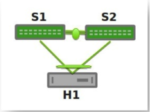
You can see an example of how to set up this configuration by running cumulus@switch:~$ net example clag basic-clag.
The two switches, S1 and S2, known as peer switches, cooperate so that they appear as a single device to host H1’s bond. H1 distributes traffic between the two links to S1 and S2 in any way that you configure on the host. Similarly, traffic inbound to H1 can traverse S1 or S2 and arrive at H1.
MLAG Requirements
MLAG has these requirements:
There must be a direct connection between the two peer switches implementing MLAG (S1 and S2). This is typically a bond for increased reliability and bandwidth.
There must be only two peer switches in one MLAG configuration, but you can have multiple configurations in a network for switch-to-switch MLAG (see below).
You must specify a unique
clag-idfor every dual-connected bond on each peer switch; the value must be between 1 and 65535 and must be the same on both peer switches in order for the bond to be considered dual-connected.The dual-connected devices (servers or switches) can use LACP (IEEE 802.3ad or 802.1ax) to form the bond. In this case, the peer switches must also use LACP.
Both switches in the MLAG pair must be identical; they must both be the same model of switch and run the same Cumulus Linux release.
Cumulus Linux does not support MLAG with 802.1X; the switch cannot synchronize 802.1X authenticated MAC addresses over the peerlink.
If for some reason you cannot use LACP, you can also use balance-xor mode to dual-connect host-facing bonds in an MLAG environment. If you do, you must still configure the same
clag-idparameter on the MLAG bonds, and it must be the same on both MLAG switches. Otherwise, the MLAG switch pair treats the bonds as if they are single-connected.
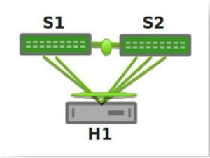
More elaborate configurations are also possible. The number of links between the host and the switches can be greater than two, and does not have to be symmetrical:
Additionally, because S1 and S2 appear as a single switch to other bonding devices, you can also connect pairs of MLAG switches to each other in a switch-to-switch MLAG setup:
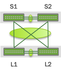
In this case, L1 and L2 are also MLAG peer switches, and present a two-port bond from a single logical system to S1 and S2. S1 and S2 do the same as far as L1 and L2 are concerned. For a switch-to-switch MLAG configuration, each switch pair must have a unique system MAC address. In the above example, switches L1 and L2 each have the same system MAC address configured. Switch pair S1 and S2 each have the same system MAC address configured; however, it is a different system MAC address than the one used by the switch pair L1 and L2.
LACP and Dual-Connectedness
For MLAG to operate correctly, the peer switches must know which links are dual-connected or are connected to the same host or switch. To do this, specify a clag-id for every dual-connected bond on each peer switch; the clag-id must be the same for the corresponding bonds on both peer switches. Typically, Link Aggregation Control Protocol (LACP), the IEEE standard protocol for managing bonds, is used for verifying dual-connectedness. LACP runs on the dual-connected device and on each of the peer switches. On the dual-connected device, the only configuration requirement is to create a bond that is managed by LACP.
However, if for some reason you cannot use LACP in your environment, you can configure the bonds in balance-xor mode. When using balance-xor mode to dual-connect host-facing bonds in an MLAG environment, you must configure the clag-id parameter on the MLAG bonds, which must be the same on both MLAG switches. Otherwise, the bonds are treated by the MLAG switch pair as if they are single-connected. In short, dual-connectedness is solely determined by matching clag-id and any misconnection will not be detected.
On each of the peer switches, you must place the links that are connected to the dual-connected host or switch in the bond. This is true even if the links are a single port on each peer switch, where each port is placed into a bond, as shown below:
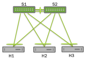
All of the dual-connected bonds on the peer switches have their system ID set to the MLAG system ID. Therefore, from the point of view of the hosts, each of the links in its bond is connected to the same system, and so the host uses both links.
Each peer switch periodically makes a list of the LACP partner MAC addresses for all of their bonds and sends that list to its peer (using the clagd service; see below). The LACP partner MAC address is the MAC address of the system at the other end of a bond (hosts H1, H2, and H3 in the figure above). When a switch receives this list from its peer, it compares the list to the LACP partner MAC addresses on its switch. If any matches are found and the clag-id for those bonds match, then that bond is a dual-connected bond. You can also find the LACP partner MAC address by the running net show bridge macs command or by examining the /sys/class/net/<bondname>/bonding/ad_partner_mac sysfs file for each bond.
Configure MLAG
To configure MLAG, you need to:
- Create a bond that uses LACP, on the dual-connected devices.
- Configure the interfaces, including bonds, VLANs, bridges and peer links, on each peer switch.
MLAG synchronizes the dynamic state between the two peer switches but it does not synchronize the switch configurations. After modifying the configuration of one peer switch, you must make the same changes to the configuration on the other peer switch. This applies to all configuration changes, including:
- Port configuration; for example, VLAN membership, MTU, and bonding parameters.
- Bridge configuration; for example, spanning tree parameters or bridge properties.
- Static address entries; for example, static FDB entries and static IGMP entries.
- QoS configuration; for example, ACL entries.
You can verify the configuration of VLAN membership with the net show clag verify-vlans verbose command.
Click to see the output ...
cumulus@leaf01:~$ net show clag verify-vlans verbose
Our Bond Interface   VlanId   Peer Bond Interface
------------------   ------   -------------------
server01                  1   server01
server01                 10   server01
server01                 20   server01
server01                 30   server01
server01                 40   server01
server01                 50   server01
uplink                    1   uplink
uplink                   10   uplink
uplink                   20   uplink
uplink                   30   uplink
uplink                   40   uplink
uplink                   50   uplink
uplink                  100   uplink
uplink                  101   uplink
uplink                  102   uplink
uplink                  103   uplink
uplink                  104   uplink
...
Reserved MAC Address Range
To prevent MAC address conflicts with other interfaces in the same bridged network, Cumulus Linux has a reserved range of MAC addresses specifically to use with MLAG. This range of MAC addresses is 44:38:39:ff:00:00 to 44:38:39:ff:ff:ff. Use this range of MAC addresses when configuring MLAG.
- You cannot use the same MAC address for different MLAG pairs. Make sure you specify a different
clag sys-macsetting for each MLAG pair in the network. - You cannot use multicast MAC addresses as the
clagd-sys-mac. - If you configure MLAG with NCLU commands, Cumulus Linux does not check against a possible collision with VLANs outside the default reserved range when creating the peer link interfaces, in case the reserved VLAN range has been modified.
Configure the Host or Switch
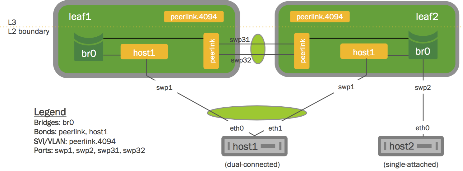
On your dual-connected device, create a bond that uses LACP. The method you use varies with the type of device you are configuring. The following image is a basic MLAG configuration, showing all the essential elements; a more detailed two-leaf/two-spine configuration is shown below.
Configure the Interfaces
Place every interface that connects to the MLAG pair from a dual-connected device into a bond, even if the bond contains only a single link on a single physical switch (even though the MLAG pair contains two or more links). Layer 2 data travels over this bond. In the examples throughout this chapter, peerlink is the name of the bond.
Single-attached hosts, also known as orphan ports, can be just a member of the bridge.
Additionally, configure the fast mode of LACP on the bond to allow more timely updates of the LACP state. These bonds are then placed in a bridge, which must include the peer link between the switches.
To enable communication between the clagd services on the peer switches, do the following:
- Choose an unused VLAN (also known as a switched virtual interface or SVI here).
- Assign the SVI an unrouteable link-local address to give the peer switches layer 3 connectivity between each other.
- Configure the VLAN as a VLAN subinterface on the peer link bond rather than the VLAN-aware bridge, called peerlink. If you’re configuring the subinterface with NCLU, the VLAN subinterface is named 4094 by default (the subinterface named peerlink.4094 below). If you are configuring the peer link without NCLU, use 4094 for the peer link VLAN if possible. This ensures that the VLAN is completely independent of the bridge and spanning tree forwarding decisions.
- Include untagged traffic on the peer link, as this avoids issues with STP.
- Specify a backup interface, which is any layer 3 backup interface for your peer links in case the peer link goes down. While a backup interface is optional, it’s best to configure one. More information about configuring the backup link and understanding various redundancy scenarios is available below.
For example, if peerlink is the inter-chassis bond, and VLAN 4094 is the peer link VLAN, configure peerlink.4094 as follows:
Cumulus Linux 3.7.6 and earlier
cumulus@leaf01:~$ net add bond peerlink bond slaves swp49-50
cumulus@leaf01:~$ net add interface peerlink.4094 ip address 169.254.1.1/30
cumulus@leaf01:~$ net add interface peerlink.4094 clag peer-ip 169.254.1.2
cumulus@leaf01:~$ net add interface peerlink.4094 clag backup-ip 192.0.2.50
cumulus@leaf01:~$ net add interface peerlink.4094 clag sys-mac 44:38:39:FF:40:94
cumulus@leaf01:~$ net pending
cumulus@leaf01:~$ net commit
The above commands save the configuration in the /etc/network/interfaces file.
auto peerlink
iface peerlink
    bond-slaves swp49 swp50

auto peerlink.4094
iface peerlink.4094
    address 169.254.1.1/30
    clagd-peer-ip 169.254.1.2
    clagd-backup-ip 192.0.2.50
    clagd-sys-mac 44:38:39:FF:40:94
Cumulus Linux 3.7.7 and later
In Cumulus Linux 3.7.7 and later, you can use MLAG unnumbered:
cumulus@leaf01:~$ net add bond peerlink bond slaves swp49-50
cumulus@leaf01:~$ net add interface peerlink.4094 clag peer-ip linklocal
cumulus@leaf01:~$ net add interface peerlink.4094 clag backup-ip 192.0.2.50
cumulus@leaf01:~$ net add interface peerlink.4094 clag sys-mac 44:38:39:FF:40:94
cumulus@leaf01:~$ net pending
cumulus@leaf01:~$ net commit
The above commands save the configuration in the /etc/network/interfaces file.
auto peerlink
iface peerlink
  bond-slaves swp49 swp50

auto peerlink.4094
iface peerlink.4094
  clagd-backup-ip 192.0.2.50
  clagd-peer-ip linklocal
  clagd-sys-mac 44:38:39:FF:40:94
Do not add VLAN 4094 to the bridge VLAN list; VLAN 4094 for the peer link subinterface cannot also be configured as a bridged VLAN with bridge VIDs under the bridge.
To enable MLAG, peerlink must be added to a traditional or VLAN-aware bridge. The commands below add peerlink to a VLAN-aware bridge:
cumulus@leaf01:~$ net add bridge bridge ports peerlink
cumulus@leaf01:~$ net pending
cumulus@leaf01:~$ net commit
This creates the following configuration in the /etc/network/interfaces file:
auto bridge
iface bridge
    bridge-ports peerlink
    bridge-vlan-aware yes
If you change the MLAG configuration by editing the interfaces file, the changes take effect when you bring the peer link interface up with ifup. Do not use systemctl restart clagd.service to apply the new configuration.
Do not use 169.254.0.1 as the MLAG peer link IP address; Cumulus Linux uses this address exclusively for BGP unnumbered interfaces.
Switch Roles and Priority Setting
Each MLAG-enabled switch in the pair has a role. When the peering relationship is established between the two switches, one switch is put into the primary role, and the other into the secondary role. When an MLAG-enabled switch is in the secondary role, it does not send STP BPDUs on dual-connected links; it only sends BPDUs on single-connected links. The switch in the primary role sends STP BPDUs on all single- and dual-connected links.
| Sends BPDUs Via | Primary | Secondary |
|---|---|---|
| Single-connected links | Yes | Yes |
| Dual-connected links | Yes | No |
By default, the role is determined by comparing the MAC addresses of the two sides of the peering link; the switch with the lower MAC address assumes the primary role. You can override this by setting the clagd-priority option for the peer link:
cumulus@leaf01:~$ net add interface peerlink.4094 clag priority 2048
cumulus@leaf01:~$ net pending
cumulus@leaf01:~$ net commit
The switch with the lower priority value is given the primary role; the default value is 32768 and the range is 0 to 65535. Read the clagd(8) and clagctl(8) man pages for more information.
When the clagd service is exited during switch reboot or the service is stopped in the primary switch, the peer switch that is in the secondary role becomes the primary.
However, if the primary switch goes down without stopping the clagd service for any reason, or if the peer link goes down, the secondary switch does not change its role. In case the peer switch is determined to be not alive, the switch in the secondary role rolls back the LACP system ID to be the bond interface MAC address instead of the clagd-sys-mac and the switch in primary role uses the clagd-sys-mac as the LACP system ID on the bonds.
clagctl Timers
The clagd service has a number of timers that you can tune for enhanced performance. The relevant timers are:
--reloadTimer <SECONDS>: The number of seconds to wait for the peer switch to become active. If the peer switch does not become active after the timer expires, the MLAG bonds will leave the initialization (protodown) state and become active. This providesclagdwith sufficient time to determine whether the peer switch is coming up or if it is permanently unreachable The default is 300 seconds.--peerTimeout <SECONDS>: The number of secondsclagdwaits without receiving any data from the peer switch before it determines that the peer is no longer active. If this parameter is not specified,clagduses ten times the locallacpPollvalue.--initDelay <SECONDS>: The number of secondsclagddelays the bring up of MLAG bonds and anycast IP addresses. The default is 10 seconds.--sendTimeout <SECONDS>: The number of secondsclagdwaits until the sending socket times out. If it takes longer than thesendTimeoutvalue to send data to the peer,clagdgenerates an exception. The default is 30 seconds.
To set a timer, use NCLU. For example, to set the peerTimeout to 900 seconds:
cumulus@switch:~$ net add interface peerlink.4094 clag args --peerTimeout 900
cumulus@switch:~$ net pending
cumulus@switch:~$ net commit
You can run clagctl params to see the settings for all of the clagd parameters.
cumulus@leaf01:~$ clagctl params
clagVersion = 1.3.0
clagDataVersion = 1.3.0
clagCmdVersion = 1.1.0
peerIp = 169.254.1.2
peerIf = peerlink.4094
sysMac = 44:38:39:ff:00:01
lacpPoll = 2
currLacpPoll = 2
peerConnect = 1
cmdConnect = 1
peerLinkPoll = 1
switchdReadyTimeout = 120
reloadTimer = 300
periodicRun = 4
priority = 1000
quiet = False
debug = 0x0
verbose = False
log = syslog
vm = True
peerPort = 5342
peerTimeout = 20
initDelay = 10
sendTimeout = 30
sendBufSize = 65536
forceDynamic = False
dormantDisable = False
redirectEnable = False
backupIp = 192.168.0.12
backupVrf = None
backupPort = 5342
vxlanAnycast = None
neighSync = True
permanentMacSync = True
cmdLine = /usr/sbin/clagd --daemon 169.254.1.2 peerlink.4094 44:38:39:FF:00:01 --priority 1000 --backupIp 192.168.0.12 --peerTimeout 900
peerlinkLearnEnable = False
cumulus@leaf01:~$
Example MLAG Configuration
The example configuration below configures two bonds for MLAG, each with a single port, a peer link that is a bond with two member ports, and three VLANs on each port.
You can see a more traditional layer 2 example configuration in NCLU; run net example clag l2-with-server-vlan-trunks. For a very basic configuration with just one pair of switches and a single host, run net example clag l2-with-server-vlan-trunks.
You configure these interfaces using NCLU, so the bridges are in VLAN-aware mode. The bridges use these Cumulus Linux-specific keywords:
bridge-vids, which defines the allowed list of tagged 802.1q VLAN IDs for all bridge member interfaces. You can specify non-contiguous ranges with a space-separated list, likebridge-vids 100-200 300 400-500.bridge-pvid, which defines the untagged VLAN ID for each port. This is commonly referred to as the native VLAN.
The bridge configurations below indicate that each bond carries tagged frames on VLANs 10, 20, 30, 40, 50, and 100 to 200 (as specified by bridge-vids), but untagged frames on VLAN 1 (as specified by bridge-pvid). Also, take note on how you configure the VLAN subinterfaces used for clagd communication (peerlink.4094 in the sample configuration below). Finally, the host configurations for server01 through server04 are not shown here. The configurations for each corresponding node are almost identical, except for the IP addresses used for managing the clagd service.
At minimum, this VLAN subinterface should not be in your layer 2 domain. Give it a very high VLAN ID (up to 4094). Read more about the range of VLAN IDs you can use.
The commands to create the configurations for both spines look like the following. Note that the clag-id and clagd-sys-mac must be the same for the corresponding bonds on spine01 and spine02:
spine01 and spine02 configuration
spine01 These commands create the following configuration in the | spine02 These commands create the following configuration in the |
Here is an example configuration for the switches leaf01 through leaf04. Note that the clag-id and clagd-sys-mac must be the same for the corresponding bonds on leaf01 and leaf02 as well as leaf03 and leaf04:
leaf01 thru leaf04 configuration
leaf01 These commands create the following configuration in the | leaf02 These commands create the following configuration in the |
leaf03 These commands create the following configuration in the | leaf04 These commands create the following configuration in the |
Disable clagd on an Interface
In the configurations above, the clagd-peer-ip and clagd-sys-mac parameters are mandatory, while the rest are optional. When mandatory clagd commands are present under a peer link subinterface, by default clagd-enable is set to yes and does not need to be specified; to disable clagd on the subinterface, set clagd-enable to no:
cumulus@spine01:~$ net add interface peerlink.4094 clag enable no
cumulus@spine01:~$ net pending
cumulus@spine01:~$ net commit
Use clagd-priority to set the role of the MLAG peer switch to primary or secondary. Each peer switch in an MLAG pair must have the same clagd-sys-mac setting. Each clagd-sys-mac setting must be unique to each MLAG pair in the network. For more details, refer to man clagd.
Check the MLAG Configuration Status
You can check the status of your MLAG configuration using the net show clag command.
cumulus@leaf01:~$ net show clag
The peer is alive
    Peer Priority, ID, and Role: 4096 44:38:39:FF:00:01 primary
     Our Priority, ID, and Role: 8192 44:38:39:FF:00:02 secondary
          Peer Interface and IP: peerlink.4094 linklocal
                      Backup IP: 192.168.1.12 (inactive)
                     System MAC: 44:38:39:FF:00:01

CLAG Interfaces
Our Interface      Peer Interface     CLAG Id   Conflicts              Proto-Down Reason
----------------   ----------------   -------   --------------------   -----------------
         server1   server1            1         -                      -
         server2   server2            2         -                      -
A command line utility called clagctl is available for interacting with a running clagd service to get status or alter operational behavior. For a detailed explanation of the utility, refer to the clagctl(8)man page.
Sample clagctl Output
The following is a sample output of the MLAG operational status displayed by clagctl:
The peer is alive
    Peer Priority, ID, and Role: 4096 44:38:39:FF:00:01 primary
     Our Priority, ID, and Role: 8192 44:38:39:FF:00:02 secondary
          Peer Interface and IP: peerlink.4094 linklocal
                      Backup IP: 192.168.1.12 (inactive)
                     System MAC: 44:38:39:FF:00:01
CLAG Interfaces
Our Interface      Peer Interface     CLAG Id   Conflicts              Proto-Down Reason
----------------   ----------------   -------   --------------------   -----------------
         server1   server1            1         -                      -
         server2   server2            2         -                      -
Configure MLAG with a Traditional Mode Bridge
You can configure MLAG with a bridge in traditional mode instead of VLAN-aware mode.
To configure MLAG with a traditional mode bridge, the peer link and all dual-connected links must be configured as untagged/native ports on a bridge (note the absence of any VLANs in the bridge-ports line and the lack of the bridge-vlan-aware parameter below):
auto br0
iface br0
    bridge-ports peerlink spine1-2 host1 host2
The following example shows you how to allow VLAN 100 across the peer link:
auto br0.100
iface br0.100
    bridge-ports peerlink.100 bond1.100
In an MLAG and traditional bridge configuration, NVIDIA recommends that you set bridge learning to off on all VLANs over the peerlink except for the layer 3 peerlink subinterface; for example:
...
auto peerlink
iface peerlink
    bridge-learning off

auto peerlink.1510
iface peerlink.1510
    bridge-learning off

auto peerlink.4094
iface peerlink.4094
...
For a deeper comparison of traditional versus VLAN-aware bridge modes, read this knowledge base article.
Peer Link Interfaces and the protodown State
In addition to the standard UP and DOWN administrative states, an interface that is a member of an MLAG bond can also be in a protodown state. When MLAG detects a problem that might result in connectivity issues such as traffic black-holing or a network meltdown if the link carrier was left in an UP state, it can put that interface into protodown state. Such connectivity issues include:
- When the peer link goes down but the peer switch is up (that is, the backup link is active).
- When the bond is configured with an MLAG ID, but the
clagdservice is not running (whether it was deliberately stopped or simply died). - When an MLAG-enabled node is booted or rebooted, the MLAG bonds are placed in a
protodownstate until the node establishes a connection to its peer switch, or five minutes have elapsed.
When an interface goes into a protodown state, it results in a local OPER DOWN (carrier down) on the interface. As of Cumulus Linux 2.5.5, the protodown state can be manipulated with the ip link set command. Given its use in preventing network meltdowns, manually manipulating protodown is not recommended outside the scope of interaction with the Cumulus Linux support team.
The following ip link show command output shows an interface in protodown state. Notice that the link carrier is down (NO-CARRIER):
cumulus@switch:~$ net show bridge link swp1
3: swp1 state DOWN: <NO-CARRIER,BROADCAST,MULTICAST,MASTER,UP> mtu 9216 master pfifo_fast master host-bond1 state DOWN mode DEFAULT qlen 500 protodown on
   link/ether 44:38:39:00:69:84 brd ff:ff:ff:ff:ff:ff
Specify a Backup Link
You should specify a backup link for your peer links in case the peer link goes down. When this happens, the clagd service uses the backup link to check the health of the peer switch. The backup link is specified in the clagd-backup-ip parameter.
In an anycast VTEP environment, if you do not specify the clagd-backup-ip parameter, large convergence times (around 5 minutes) can result when the primary MLAG switch is powered off. Then the secondary switch must wait until the reload delay timer expires (which defaults to 300 seconds, or 5 minutes) before bringing up a VNI with its unique loopback IP.
To configure a backup link, add clagd-backup-ip <ADDRESS> to the peer link configuration:
cumulus@spine01:~$ net add interface peerlink.4094 clag backup-ip 192.0.2.50
cumulus@spine01:~$ net pending
cumulus@spine01:~$ net commit
The backup IP address must be different than the peer link IP address (clagd-peer-ip). It must be reachable by a route that does not use the peer link and it must be in the same network namespace as the peer link IP address.
Use the switch’s loopback or management IP address for this purpose. Which one should you choose?
- If your MLAG configuration has routed uplinks (a modern approach to the data center fabric network), then configure
clagdto use the peer switch loopback address for the health check. When the peer link is down, the secondary switch must route towards the loopback address using uplinks (towards spine layer). If the primary switch is also suffering a more significant problem (for example,switchdis unresponsive /or stopped), then the secondary switch eventually promotes itself to primary and traffic now flows normally.
To ensure IP connectivity between the loopbacks, you must carefully consider what implications this has on the BGP ASN configured:
- The two MLAG member switches must use unique BGP ASNs, or,
- If the two MLAG member switches use the same BGP ASN, then you must bypass the BGP loop prevention check on AS_PATH attribute.
- If your MLAG configuration has bridged uplinks (such as a campus network or a large, flat layer 2 network), then configure
clagdto use the peer switch eth0 address for the health check. When the peer link is down, the secondary switch must route towards the eth0 address using the OOB network (provided you have implemented an OOB network).
You can also specify the backup UDP port. The port defaults to 5342, but you can configure it as an argument in clagd-args using --backupPort <PORT>.
cumulus@spine01:~$ net add interface peerlink.4094 clag args --backupPort 5400
cumulus@spine01:~$ net pending
cumulus@spine01:~$ net commit
To see the backup IP address, run the net show clag command:
cumulus@spine01:~$ net show clag
The peer is alive
     Our Priority, ID, and Role: 32768 44:38:39:00:00:41 primary
    Peer Priority, ID, and Role: 32768 44:38:39:00:00:42 secondary
          Peer Interface and IP: peerlink.4094 linklocal
                      Backup IP: 192.168.0.22 (active)
                     System MAC: 44:38:39:FF:40:90

CLAG Interfaces
Our Interface      Peer Interface     CLAG Id   Conflicts              Proto-Down Reason
----------------   ----------------   -------   --------------------   -----------------
       leaf03-04   leaf03-04          1034      -                      -
       exit01-02   -                  2930      -                      -
       leaf01-02   leaf01-02          1012      -                      -
Specify a Backup Link to a VRF
You can configure the backup link to a VRF or management VRF. Include the name of the VRF or management VRF with the clagd-backup-ip command. Here is a sample configuration:
cumulus@spine01:~$ net add interface peerlink.4094 clag backup-ip 192.168.0.22 vrf mgmt
cumulus@spine01:~$ net pending
cumulus@spine01:~$ net commit
You cannot use the VRF on a peer link subinterface.
Verify the backup link by running the net show clag backup-ip command:
cumulus@leaf01:~$ net show clag backup-ip
Backup info:
IP: 192.168.0.12; State: active; Role: primary
Peer priority and id: 32768 44:38:39:00:00:12; Peer role: secondary
The MLAG healthCheck module listens on UDP port 5342. If you have not configured a backup VRF, the module listens on all VRFs, which is normal UDP socket behavior. Make sure to configure a backup link and backup VRF so that the MLAG healthcheck module only listens on the backup VRF.
Comparing VRF and Management VRF Configurations
The configuration for both a VRF and management VRF is exactly the same. The following example shows a configuration where the backup interface is in a VRF:
cumulus@leaf01:~$ net show configuration
...
auto swp52s0
iface swp52s0
    address 192.0.2.1/24
    vrf green

auto green
iface green
    vrf-table auto

auto peer5.4000
iface peer5.4000
    address 192.0.2.15/24
    clagd-peer-ip linklocal
    clagd-backup-ip 192.0.2.2 vrf green
    clagd-sys-mac 44:38:39:01:01:01
...
You can verify the configuration with the net show clag status verbose command:
cumulus@leaf01:~$ net show clag status verbose
The peer is alive
    Peer Priority, ID, and Role: 32768 00:02:00:00:00:13 primary
     Our Priority, ID, and Role: 32768 c4:54:44:f6:44:5a secondary
          Peer Interface and IP: peer5.4000 linklocal
                      Backup IP: 192.0.2.2 vrf green (active)
                     System MAC: 44:38:39:01:01:01

CLAG Interfaces
Our Interface      Peer Interface     CLAG Id   Conflicts              Proto-Down Reason
----------------   ----------------   -------   --------------------   -----------------
           bond4   bond4              4         -                      -
           bond1   bond1              1         -                      -
           bond2   bond2              2         -                      -
           bond3   bond3              3         -                      -

...
Monitor Dual-Connected Peers
Upon receipt of a valid message from its peer, the switch knows that clagd is alive and executing on that peer. This causes clagd to change the system ID of each bond that is assigned a clag-id from the default value (the MAC address of the bond) to the system ID assigned to both peer switches. This makes the hosts connected to each switch act as if they are connected to the same system so that they use all ports within their bond. Additionally, clagd determines which bonds are dual-connected and modifies the forwarding and learning behavior to accommodate these dual-connected bonds.
If the peer does not receive any messages for three update intervals, then that peer switch is assumed to no longer be acting as an MLAG peer. In this case, the switch reverts all configuration changes so that it operates as a standard non-MLAG switch. This includes removing all statically assigned MAC addresses, clearing the egress forwarding mask, and allowing addresses to move from any port to the peer port. After a message is again received from the peer, MLAG operation starts again as described earlier. You can configure a custom timeout setting by adding --peerTimeout <VALUE> to clagd-args, like this:
cumulus@spine01:~$ net add interface peerlink.4094 clag args --peerTimeout 900
cumulus@spine01:~$ net pending
cumulus@spine01:~$ net commit
After bonds are identified as dual-connected, clagd sends more information to the peer switch for those bonds. The MAC addresses (and VLANs) that are dynamically learned on those ports are sent along with the LACP partner MAC address for each bond. When a switch receives MAC address information from its peer, it adds MAC address entries on the corresponding ports. As the switch learns and ages out MAC addresses, it informs the peer switch of these changes to its MAC address table so that the peer can keep its table synchronized. Periodically, at 45% of the bridge ageing time, a switch sends its entire MAC address table to the peer, so that peer switch can verify that its MAC address table is properly synchronized.
The switch sends an update frequency value in the messages to its peer, which tells clagd how often the peer will send these messages. You can configure a different frequency by adding --lacpPoll <SECONDS> to clagd-args:
cumulus@spine01:~$ net add interface peerlink.4094 clag args --lacpPoll 900
cumulus@spine01:~$ net pending
cumulus@spine01:~$ net commit
Configure Layer 3 Routed Uplinks
In this scenario, the spine switches connect at layer 3, as shown in the image below. Alternatively, the spine switches can be singly connected to each core switch at layer 3 (not shown below).
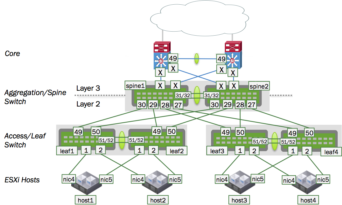
In this design, the spine switches route traffic between the server hosts in the layer 2 domains and the core. The servers (host1 thru host4) each have a layer 2 connection up to the spine layer where the default gateway for the host subnets resides. However, since the spine switches as gateway devices communicate at layer 3, you need to configure a protocol such as VRR (virtual router redundancy) between the spine switch pair to support active/active forwarding.
Then, to connect the spine switches to the core switches, you need to determine whether the routing is static or dynamic. If it is dynamic, you must choose which protocol - OSPF or BGP - to use.
When enabling a routing protocol in an MLAG environment, it is also necessary to manage the uplinks, because by default MLAG is not aware of layer 3 uplink interfaces. In the event of a peer link failure, MLAG does not remove static routes or bring down a BGP or OSPF adjacency unless a separate link state daemon such as ifplugd is used.
MLAG and Peer Link Peering
When using MLAG with VRR, set up a routed adjacency across the peerlink.4094 interface. If a routed connection is not built across the peer link, then during uplink failure on one of the switches in the MLAG pair, egress traffic can be blackholed if it hashes to the leaf whose uplinks are down.
To set up the adjacency, configure a BGP or OSPF unnumbered peering, as appropriate for your network.
For example, if you are using BGP, use a configuration like this:
cumulus@switch:~$ net add bgp neighbor peerlink.4094 interface remote-as internal
cumulus@switch:~$ net commit
If you are using OSPF, use a configuration like this:
cumulus@switch:~$ net add interface peerlink.4094 ospf area 0.0.0.1
cumulus@switch:~$ net commit
If you are using EVPN and MLAG, you need to enable the EVPN address family across the peerlink.4094 interface as well:
cumulus@switch:~$ net add bgp neighbor peerlink.4094 interface remote-as internal
cumulus@switch:~$ net add bgp l2vpn evpn neighbor peerlink.4094 activate
cumulus@switch:~$ net commit
Be aware of an existing issue when you use NCLU to create an iBGP peering, it creates an eBGP peering instead. For more information, see this release note.
MLAG Routing Support
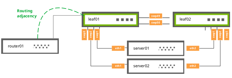
In addition to the routing adjacency over the peer link, Cumulus Linux supports routing adjacencies from attached network devices to MLAG switches under the following conditions:
- The router must physically attach to a single interface of a switch.
- The attached router must peer directly to a local address on the physically connected switch.
The router cannot:
- Attach to the switch over a MLAG bond interface.
- Form routing adjacencies to a virtual address (VRR or VRRP).
IGMP Snooping with MLAG
IGMP snooping processes IGMP reports received on a bridge port in a bridge to identify hosts that are configured to receive multicast traffic destined to that group. An IGMP query message received on a port is used to identify the port that is connected to a router and configured to receive multicast traffic.
IGMP snooping is enabled by default on the bridge. IGMP snooping multicast database entries and router port entries are synced to the peer MLAG switch. If there is no multicast router in the VLAN, you can configure the IGMP querier on the switch to generate IGMP query messages. For more information, read the IGMP and MLD Snooping chapter.
In an MLAG configuration, the switch in the secondary role does not send IGMP queries, even though the configuration is identical to the switch in the primary role. This is expected behavior, as there can be only one querier on each VLAN. Once the querier on the primary switch stops transmitting, the secondary switch starts transmitting.
Monitor the Status of the clagd Service
Due to the critical nature of the clagd service, systemd continuously monitors the status of clagd. systemd monitors the clagd service through the use of notify messages every 30 seconds. If the clagd service dies or becomes unresponsive for any reason and systemd receives no messages after 60 seconds, systemd restarts clagd. systemd logs these failures in /var/log/syslog, and, on the first failure, generates a cl-support file as well.
This monitoring is automatically configured and enabled as long as clagd is enabled (that is, clagd-peer-ip and clagd-sys-mac are configured for an interface) and the clagd service is running. When clagd is explicitly stopped, for example with the systemctl stop clagd.service command, monitoring of clagd is also stopped.
Check clagd Status
You can check the status of clagd monitoring by using the cl-service-summary command:
cumulus@switch:~$ sudo cl-service-summary summary
The systemctl daemon 5.4 uptime: 15m
...
Service clagd        enabled    active
...
Or the systemctl status command:
cumulus@switch:~$ sudo systemctl status clagd.service
● clagd.service - Cumulus Linux Multi-Chassis LACP Bonding Daemon
   Loaded: loaded (/lib/systemd/system/clagd.service; enabled)
   Active: active (running) since Mon 2016-10-03 20:31:50 UTC; 4 days ago
     Docs: man:clagd(8)
Main PID: 1235 (clagd)
   CGroup: /system.slice/clagd.service
           ├─1235 /usr/bin/python /usr/sbin/clagd --daemon 169.254.255.2 peerlink.4094 44:38:39:FF:40:90 --prior...
           └─1307 /sbin/bridge monitor fdb

Feb 01 23:19:30 leaf01 clagd[1717]: Cleanup is executing.
Feb 01 23:19:31 leaf01 clagd[1717]: Cleanup is finished
Feb 01 23:19:31 leaf01 clagd[1717]: Beginning execution of clagd version 1.3.0
Feb 01 23:19:31 leaf01 clagd[1717]: Invoked with: /usr/sbin/clagd --daemon 169.254.255.2 peerlink.4094 44:38:39:FF:40:94 --pri...168.0.12
Feb 01 23:19:31 leaf01 clagd[1717]: Role is now secondary
Feb 01 23:19:31 leaf01 clagd[1717]: Initial config loaded
Feb 01 23:19:31 leaf01 systemd[1]: Started Cumulus Linux Multi-Chassis LACP Bonding Daemon.
Feb 01 23:24:31 leaf01 clagd[1717]: HealthCheck: reload timeout.
Feb 01 23:24:31 leaf01 clagd[1717]: Role is now primary; Reload timeout
Hint: Some lines were ellipsized, use -l to show in full.
MLAG Best Practices
For MLAG to function properly, you must configure the dual-connected host interfaces identically on the pair of peering switches. See the note above in the Configure MLAG section.
MTU in an MLAG Configuration
The best way to configure MTU in MLAG is to set the MTU at the system level, as per the documentation for setting a policy for a global system MTU.
Otherwise, traffic is determined by the bridge MTU. Bridge MTU in turn is determined by the lowest MTU setting of an interface that is a member of the bridge. If you want to set an MTU other than the default of 1500 bytes, you must configure the MTU on each physical interface and bond interface that are members of the MLAG bridges in the entire bridged domain.
For example, if an MTU of 9216 is desired through the MLAG domain in the example shown above, on all four leaf switches, configure mtu 9216 for each of the following bond interfaces, as they are members of the bridge named bridge: peerlink, uplink, server01.
cumulus@leaf01:~$ net add bond peerlink mtu 9216
cumulus@leaf01:~$ net add bond uplink mtu 9216
cumulus@leaf01:~$ net add bond server01 mtu 9216
cumulus@leaf01:~$ net pending
cumulus@leaf01:~$ net commit
The above commands produce the following configuration in the
/etc/network/interfaces file:
auto bridge
iface bridge
    bridge-ports peerlink uplink server01

auto peerlink
iface peerlink
    mtu 9216

auto server01
iface server01
    mtu 9216

auto uplink
iface uplink
    mtu 9216
Likewise, to ensure the MTU 9216 path is respected through the spine switches above, also change the MTU setting for bridge bridge by configuring mtu 9216 for each of the following members of bridge *bridge on both spine01 and spine02: leaf01-02, leaf03-04, exit01-02, peerlink.
cumulus@spine01:~$ net add bond leaf01-02 mtu 9216
cumulus@spine01:~$ net add bond leaf03-04 mtu 9216
cumulus@spine01:~$ net add bond exit01-02 mtu 9216
cumulus@spine01:~$ net add bond peerlink mtu 9216
cumulus@spine01:~$ net pending
cumulus@spine01:~$ net commit
The above commands produce the following configuration in the /etc/network/interfaces file:
auto bridge
iface bridge
    bridge-ports leaf01-02 leaf03-04 exit01-02 peerlink

auto exit01-02
iface exit01-02
    mtu 9216

auto leaf01-02
iface leaf01-02
    mtu 9216

auto leaf03-04
iface leaf03-04
    mtu 9216

auto peerlink
iface peerlink
    mtu 9216
Peer Link Sizing
The peer link carries very little traffic when compared to the bandwidth consumed by dataplane traffic. In a typical MLAG configuration, most every connection between the two switches in the MLAG pair is dual-connected, so the only traffic going across the peer link is traffic from the clagd process and some LLDP or LACP traffic; the traffic received on the peer link is not forwarded out of the dual-connected bonds.
However, there are some instances where a host is connected to only one switch in the MLAG pair; for example:
- You have a hardware limitation on the host where there is only one PCIE slot, and therefore, one NIC on the system, so the host is only single-connected across that interface.
- The host does not support 802.3ad and you cannot create a bond on it.
- You are accounting for a link failure, where the host may become single connected until the failure is rectified.
In general, you need to determine how much bandwidth is traveling across the single-connected interfaces, and allocate half of that bandwidth to the peer link. We recommend half of the single-connected bandwidth because, on average, one half of the traffic destined to the single-connected host arrives on the switch directly connected to the single-connected host and the other half arrives on the switch that is not directly connected to the single-connected host. When this happens, only the traffic that arrives on the switch that is not directly connected to the single-connected host needs to traverse the peer link, which is how you calculate 50% of the traffic.
In addition, you might want to add extra links to the peer link bond to handle link failures in the peer link bond itself.
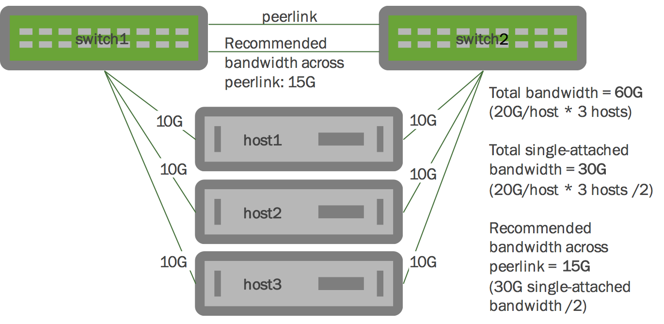
In the illustration below, each host has two 10G links, with each 10G link going to each switch in the MLAG pair. Each host has 20G of dual-connected bandwidth, so all three hosts have a total of 60G of dual-connected bandwidth. We recommend you allocate at least 15G of bandwidth to each peer link bond, which represents half of the single-connected bandwidth.
Scaling this example out to a full rack, when planning for link failures, you need only allocate enough bandwidth to meet your site’s strategy for handling failure scenarios. Imagine a full rack with 40 servers and two switches. You might plan for four to six servers to lose connectivity to a single switch and become single connected before you respond to the event. So expanding upon our previous example, if you have 40 hosts each with 20G of bandwidth dual-connected to the MLAG pair, you might allocate 20G to 30G of bandwidth to the peer link - which accounts for half of the single-connected bandwidth for four to six hosts.
Failover Redundancy Scenarios
To get a better understanding of how STP and LACP behave in response to various failover redundancy scenarios, read this knowledge base article.
STP Interoperability with MLAG
Always enable STP in your layer 2 network.
With MLAG, enable BPDU guard on the host-facing bond interfaces. For more information about BPDU guard, see BPDU Guard and Bridge Assurance.
Run the net show <interface> spanning-tree command to display MLAG information useful for debugging:
cumulus@switch:~$ net show bridge spanning-tree
bridge:peerlink CIST info
    enabled            yes                     role                 Designated
    port id            8.002                   state                forwarding
    ..............
    bpdufilter port    no
    clag ISL           yes                     clag ISL Oper UP     yes
    clag role          primary                 clag dual conn mac   00:00:00:00:00:00
    clag remote portID F.FFF                   clag system mac      44:38:39:FF:40:90
Best Practices for STP with MLAG
The STP global configuration must be the same on both peer switches.
The STP configuration for dual-connected ports should be the same on both peer switches.
To minimize convergence times when a link transitions to the forwarding state, configure the edge ports (for tagged and untagged frames) with PortAdminEdge and BPDU guard enabled.
The STP priority must be the same on both peer switches. You set the priority with this command:
cumulus@switch:~$ net add bridge stp treeprio PRIORITY_VALUE
cumulus@switch:~$ net commit
Use NCLU (
net) commands for all spanning tree configurations, including bridge priority, path cost and so forth. Do not usebrctlcommands for spanning tree, except forbrctl stp on/off, as changes are not reflected tomstpdand can create conflicts.
Troubleshooting
Here are some troubleshooting tips.
View the MLAG Log File
By default, when clagd is running, it logs its status to the /var/log/clagd.log file and syslog. Example log file output is below:
cumulus@spine01:~$ sudo tail /var/log/clagd.log
2016-10-03T20:31:50.471400+00:00 spine01 clagd[1235]: Initial config loaded
2016-10-03T20:31:52.479769+00:00 spine01 clagd[1235]: The peer switch is active.
2016-10-03T20:31:52.496490+00:00 spine01 clagd[1235]: Initial data sync to peer done.
2016-10-03T20:31:52.540186+00:00 spine01 clagd[1235]: Role is now primary; elected
2016-10-03T20:31:54.250572+00:00 spine01 clagd[1235]: HealthCheck: role via backup is primary
2016-10-03T20:31:54.252642+00:00 spine01 clagd[1235]: HealthCheck: backup active
2016-10-03T20:31:54.537967+00:00 spine01 clagd[1235]: Initial data sync from peer done.
2016-10-03T20:31:54.538435+00:00 spine01 clagd[1235]: Initial handshake done.
2016-10-03T20:31:58.527464+00:00 spine01 clagd[1235]: leaf03-04 is now dual connected.
2016-10-03T22:47:35.255317+00:00 spine01 clagd[1235]: leaf01-02 is now dual connected.
Large Packet Drops on the Peer Link Interface
A large volume of packet drops across one of the peer link interfaces can be expected. These drops serve to prevent looping of BUM (broadcast, unknown unicast, multicast) packets. When a packet is received across the peer link, if the destination lookup results in an egress interface that is a dual-connected bond, the switch does not forward the packet to prevent loops. This results in a drop being recorded on the peer link.
You can detect this issue by running the net show counters or the ethtool -S <interface> command.
Using NCLU, the number of dropped packets is displayed in the RX_DRP column when you run net show counters:
cumulus@switch:~$ net show counters

Kernel Interface table
Iface              MTU    Met    RX_OK    RX_ERR    RX_DRP    RX_OVR    TX_OK    TX_ERR    TX_DRP    TX_OVR  Flg
---------------  -----  -----    -------  --------  --------  --------  -------  --------  --------  ------  -----
peerlink        1500       0      19226721     0      2952460  0       55115330     0       364      0       BMmRU
peerlink.4094   1500       0      0            0      0        0       5379243      0       0        0       BMRU
swp51           1500       0      6587220      0      2129676  0       38957769     0       202      0       BMsRU
swp52           1500       0      12639501     0      822784   0       16157561     0       162      0       BMsRU
When you run ethtool -S on a peer link interface, the drops are indicated by the HwIfInDiscards counter:
cumulus@switch:~$ sudo ethtool -S swp51
NIC statistics:
HwIfInOctets: 669507330
HwIfInUcastPkts: 658871
HwIfInBcastPkts: 2231559
HwIfInMcastPkts: 3696790
HwIfOutOctets: 2752224343
HwIfOutUcastPkts: 1001632
HwIfOutMcastPkts: 3743199
HwIfOutBcastPkts: 34212938
HwIfInDiscards: 2129675
Duplicate LACP Partner MAC Warning
When you run clagctl, you may see output like this:
bond01 bond01 52 duplicate lacp - partner mac
This occurs when you have multiple LACP bonds between the same two LACP endpoints - for example, an MLAG switch pair is one endpoint and an ESXi host is another. These bonds have duplicate LACP identifiers, which are MAC addresses. This same warning could be triggered when you have a cabling or configuration error.
Caveats and Errata
- If both the backup and peer connectivity are lost within a 30-second window, the switch in the secondary role misinterprets the event sequence, believing the peer switch is down, so it takes over as the primary.
- MLAG is disabled on the chassis, including the Facebook Backpack and EdgeCore OMP-800.